LATEST F1 NEWS
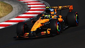 Norris beats Verstappen and Antonelli to victory in Hungary
 Albon reflects on journey to 100 races with Williams
 Leon claims maiden F2 Feature Race win in Budapest
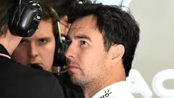 OFFICIAL GRID: Who starts where for the Hungarian GP
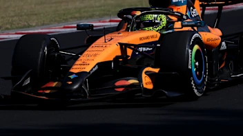 LiveLIVE COVERAGE: Norris takes first Grand Prix win of the season
 Slater beats Ugochukwu to F3 win and title lead in Budapest
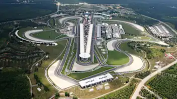 Malaysia confirmed to join 2026 F1 calendar as Bahrain host
 Why Hungary pole might not be 'turning point' for McLaren
 BettingBetting mistakes to avoid during the Hungarian GP
 BettingFinal Hungarian Grand Prix predictions and latest odds
 Antonelli admits Mercedes losing ground in development race
 Hulkenberg concerned by ‘bigger gap’ to rivals in Hungary
 UnlockedWhat are the tyre strategy options for the Hungarian GP?
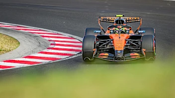 BettingOur four-leg Bet Builder for the Hungarian Grand Prix
 What the teams said – Qualifying in Hungary
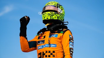 UnlockedWhat To Watch For in the Hungarian Grand Prix